Interface Notation
Interface is represented by a circle as shown in the following figure. It has a name which is generally written below the circle.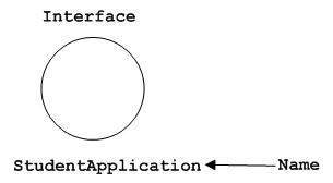 Interface is used to describe the functionality without
implementation. Interface is just like
a template where you define different functions, not the implementation.
When a class implements the interface, it also implements the
functionality as per requirement.
Interface is used to describe the functionality without
implementation. Interface is just like
a template where you define different functions, not the implementation.
When a class implements the interface, it also implements the
functionality as per requirement.Collaboration Notation
Collaboration is represented by a dotted eclipse as shown in the following figure. It has a name written inside the eclipse.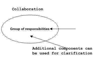 Collaboration represents responsibilities. Generally, responsibilities are in a group.
Use Case Notation
Use case is represented as an eclipse with a name inside it. It may contain additional responsibilities.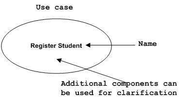 Use case is used to capture high level functionalities of a system.
Actor Notation
An actor can be defined as some internal or external entity that interacts with the system.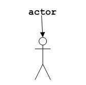 An actor is used in a use case diagram to describe the internal or external entities.
Initial State Notation
Initial state is defined to show the start of a process. This notation is used in almost all diagrams.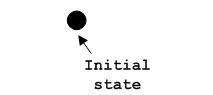 The usage of Initial State Notation is to show the starting point of a process.
Final State Notation
Final state is used to show the end of a process. This notation is also used in almost all diagrams to describe the end. The usage of Final State Notation is to show the termination point of a process.
Active Class Notation
Active class looks similar to a class with a solid border. Active class is generally used to describe the concurrent behavior of a system.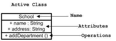 Active class is used to represent the concurrency in a system.
Component Notation
A component in UML is shown in the following figure with a name inside. Additional elements can be added wherever required.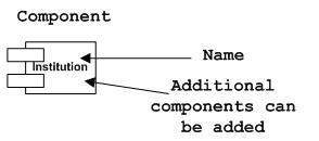 Component is used to represent any part of a system for which UML diagrams are made.
Node Notation
A node in UML is represented by a square box as shown in the following figure with a name. A node represents the physical component of the system.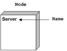 Node is used to represent the physical part of a system such as the server, network, etc.
Behavioral Things
Dynamic parts are one of the most important elements in UML. UML has a set of powerful features to represent the dynamic part of software and non-software systems. These features include interactions and state machines.Interactions can be of two types −
- Sequential (Represented by sequence diagram)
- Collaborative (Represented by collaboration diagram)
Interaction Notation
Interaction is basically a message exchange between two UML components. The following diagram represents different notations used in an interaction.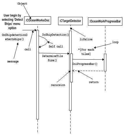 Interaction is used to represent the communication among the components of a system.
State Machine Notation
State machine describes the different states of a component in its life cycle. The notations are described in the following diagram.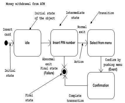 State machine is used to describe different states of a system
component. The state can be active, idle, or any other depending upon
the situation.
State machine is used to describe different states of a system
component. The state can be active, idle, or any other depending upon
the situation.Grouping Things
Organizing the UML models is one of the most important aspects of the design. In UML, there is only one element available for grouping and that is package.Package Notation
Package notation is shown in the following figure and is used to wrap the components of a system.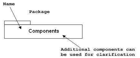
Annotational Things
In any diagram, explanation of different elements and their functionalities are very important. Hence, UML has notes notation to support this requirement.Note Notation
This notation is shown in the following figure. These notations are used to provide necessary information of a system.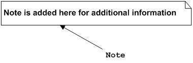
Relationships
A model is not complete unless the relationships between elements are described properly. The Relationship gives a proper meaning to a UML model. Following are the different types of relationships available in UML.- Dependency
- Association
- Generalization
- Extensibility
Dependency Notation
Dependency is an important aspect in UML elements. It describes the dependent elements and the direction of dependency.Dependency is represented by a dotted arrow as shown in the following figure. The arrow head represents the independent element and the other end represents the dependent element.
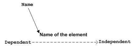 Dependency is used to represent the dependency between two elements of a system
Association Notation
Association describes how the elements in a UML diagram are associated. In simple words, it describes how many elements are taking part in an interaction.Association is represented by a dotted line with (without) arrows on both sides. The two ends represent two associated elements as shown in the following figure. The multiplicity is also mentioned at the ends (1, *, etc.) to show how many objects are associated.
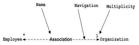 Association is used to represent the relationship between two elements of a system.
Generalization Notation
Generalization describes the inheritance relationship of the object-oriented world. It is a parent and child relationship.Generalization is represented by an arrow with a hollow arrow head as shown in the following figure. One end represents the parent element and the other end represents the child element.
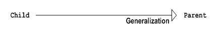 Generalization is used to describe parent-child relationship of two elements of a system.
Extensibility Notation
All the languages (programming or modeling) have some mechanism to extend its capabilities such as syntax, semantics, etc. UML also has the following mechanisms to provide extensibility features.- Stereotypes (Represents new elements)
- Tagged values (Represents new attributes)
- Constraints (Represents the boundaries)
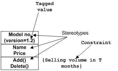 Extensibility notations are used to enhance the power of the
language. It is basically additional elements used to represent some
extra behavior of the system. These extra behaviors are not covered by
the standard available notations.
Extensibility notations are used to enhance the power of the
language. It is basically additional elements used to represent some
extra behavior of the system. These extra behaviors are not covered by
the standard available notations.인터페이스 표기법
인터페이스는 다음 그림과 같이 원으로 표시됩니다. 일반적으로 서클 아래에 쓰여지는 이름이 있습니다.인터페이스 표기법
인터페이스는 구현없이 기능을 설명하는 데 사용됩니다. 인터페이스는 구현이 아닌 다른 기능을 정의하는 템플릿과 같습니다. 클래스가 인터페이스를 구현할 때 요구 사항에 따라 기능을 구현합니다.공동 작업 표기법
협업은 다음 그림과 같이 점으로 구분 된 일식으로 표시됩니다. 그것은 일식 안에 쓰여진 이름을 가지고 있습니다.공동 작업 표기법
협업은 책임을 나타냅니다. 일반적으로 책임은 그룹에 속합니다.사용 사례 표기법
유스 케이스는 내부에 이름이있는 일식으로 표현됩니다. 추가 책임을 포함 할 수 있습니다.사용 사례 표기법
유스 케이스는 시스템의 고수준 기능을 포착하는 데 사용됩니다.액터 표기법
액터는 시스템과 상호 작용하는 내부 또는 외부 엔티티로 정의 할 수 있습니다.액터 표기법
액터는 유스 케이스 다이어그램에서 내부 또는 외부 엔티티를 설명하는 데 사용됩니다.초기 상태 표기법
초기 상태는 프로세스의 시작을 나타 내기 위해 정의됩니다. 이 표기법은 거의 모든 다이어그램에서 사용됩니다.초기 상태 표기법
초기 상태 표기법의 사용은 프로세스의 시작 지점을 표시하는 것입니다.최종 국가 표기법
최종 상태는 프로세스의 끝을 표시하는 데 사용됩니다. 이 표기법은 거의 모든 다이어그램에서 끝을 설명하는 데 사용됩니다.최종 상태 표기법
Final State Notation의 사용은 프로세스의 종료 지점을 표시하는 것입니다.활성 클래스 표기법
활성 클래스는 단색 테두리가있는 클래스와 유사합니다. 액티브 클래스는 일반적으로 시스템의 동시 동작을 설명하는 데 사용됩니다.활성 클래스 표기법
활성 클래스는 시스템의 동시성을 나타내는 데 사용됩니다.구성 요소 표기법
다음 그림에는 UML의 구성 요소가 이름으로 표시되어 있습니다. 필요할 때마다 추가 요소를 추가 할 수 있습니다.구성 요소 표기법
구성 요소는 UML 다이어그램이 만들어진 시스템의 모든 부분을 나타내는 데 사용됩니다.노드 표기법
UML의 노드는 이름이있는 다음 그림과 같이 사각형 상자로 표시됩니다. 노드는 시스템의 물리적 구성 요소를 나타냅니다.노드 표기법
노드는 서버, 네트워크 등과 같은 시스템의 물리적 부분을 나타내는 데 사용됩니다.행동주의 사항
동적 인 부분은 UML에서 가장 중요한 요소 중 하나입니다. UML에는 소프트웨어 및 비 소프트웨어 시스템의 동적 부분을 나타내는 강력한 기능 세트가 있습니다. 이러한 기능에는 상호 작용 및 상태 시스템이 포함됩니다.
상호 작용은 두 가지 유형이 될 수 있습니다.
순차 (시퀀스 다이어그램으로 표현)
공동 작업 (공동 작업 다이어그램으로 표현)
상호 작용 표기법
상호 작용은 기본적으로 두 UML 구성 요소 간의 메시지 교환입니다. 다음 다이어그램은 상호 작용에 사용되는 다른 표기법을 나타냅니다.상호 작용 표기법
상호 작용은 시스템 구성 요소 간의 통신을 나타내는 데 사용됩니다.상태 머신 표기법
상태 시스템은 라이프 사이클에서 구성 요소의 여러 상태를 설명합니다. 표기법은 다음 도표에 설명되어 있습니다.상태 기계 표기법
상태 시스템은 시스템 구성 요소의 여러 상태를 설명하는 데 사용됩니다. 상태는 활성 상태, 유휴 상태 또는 상황에 따라 다른 상태 일 수 있습니다.그룹화
UML 모델을 구성하는 것이 디자인의 가장 중요한 측면 중 하나입니다. UML에서는 그룹핑에 사용할 수있는 요소가 하나뿐이므로 패키지입니다.패키지 표기법
패키지 표기법은 다음 그림과 같으며 시스템 구성 요소를 래핑하는 데 사용됩니다.패키지 표기법특수 효과
모든 다이어그램에서 다른 요소와 기능에 대한 설명이 매우 중요합니다. 따라서 UML에는이 요구 사항을 지원하는 노트 표기법이 있습니다.노트 표기법
이 표기법은 다음 그림과 같습니다. 이 표기법은 시스템에 대해 필요한 정보를 제공하는 데 사용됩니다.노트 표기법관계
요소들 사이의 관계가 적절하게 기술되지 않으면 모델은 완전하지 않습니다. Relationship은 UML 모델에 적절한 의미를 부여합니다. 다음은 UML에서 사용할 수있는 다양한 유형의 관계입니다.
의존
협회
일반화
확장 성
종속성 표기법
종속성은 UML 요소에서 중요한 측면입니다. 종속 요소와 종속성의 방향을 설명합니다.
종속성은 다음 그림과 같이 점선으로 표시된 화살표로 표시됩니다. 화살표 머리는 독립 요소를 나타내고 다른 끝은 종속 요소를 나타냅니다.종속성 표기법
종속성은 시스템의 두 요소 사이의 종속성을 나타내는 데 사용됩니다.연결 표기법
연관은 UML 다이어그램의 요소가 어떻게 연관되는지를 설명합니다. 간단히 말해, 얼마나 많은 요소가 상호 작용에 참여 하는지를 설명합니다.
협회는 양쪽에 화살표가있는 점선으로 표시됩니다. 두 끝은 두 개의 연관된 elem을 나타냅니다.
댓글 없음:
댓글 쓰기